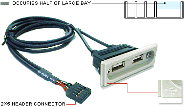
SPECIFICATIONS
PRODUCT NAME
FRONTX Dual USB Type A Internal
PRODUCT CODE
CPX108-2
BAY USAGE
Half of large bay
CONNECTORS
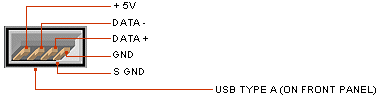
USB type A female
2x5 header connector female
CABLE
USB 2.0 cable (UL 2725)
Length - 2.5 feet (762 mm)
WIRE ASSIGNMENTS
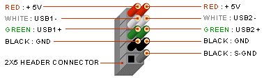
Red: + 5V / Voltage + / VCC
White: USB - / Data - / D -
Green: USB + / Data + / D +
Black: GND / Voltage - / Ground
Black: S-GND / Over Current
The S-GND wire is fatter and can be easily recognized.
The shiedings of the 2 cables are shorted (connected) internally and
converged into one S-GND wire. The connection of S-GND wire to the
header pin is optional.
HEADER CONNECTION GUIDES
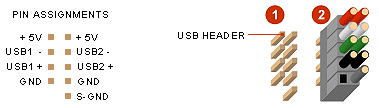
Diagram 1: On most motherboards, the USB header/pin-out consists of 9 pins
arranged in 2 rows; and each header allows for 2 USB connections (i.e.
USB1 and USB2). Normally, the pins for USB1 and USB2 are in seperate rows.
Diagram 2: Simply plug the connector onto the header, in such that;
the wires are correctly connected to the appropriate pins (i.e. wire
assignments and pin assignments are matched).
You might have to rearrange the wires to match
with the pin assignments, or change the header connector if necessary,
depending on the layout of the USB header.
On some motherboards, there is a NC pin in the USB header. You can
connect the S-GND wire onto this pin. NC simply means "no connection" and
NC pin is an "empty" pin.
2X5 PINS HEADER
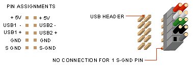
Refer to the diagram below, a 2x5 pins header has 2 S-GND pins. You can
leave one of the S-GND pins unconnected. Please make sure that the color coded
wires are connected to the correct pins. You might have to rearrange
the wires if necessary.
2X4 PINS HEADER
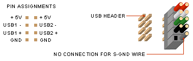
Refer to the diagram below, a 2x4 pins header has no S-GND pin. You can
leave the S-GND wire unconnected. You might have to rearrange
the wires if necessary, in such that the wire assignments and pins assignments
are matched correctly.
ACTIVE PINS NOT IN THE SAME ROW
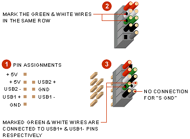
Diagram 1: On some motherboards, the 4 active pins are not arranged in
one same row.
Diagram 2: Before shifting the wires, use a marker pen to mark the green
and white wires located in the same row. It means that these 2 wires work as
a pair. The other green and white wires (unmarked) work as another pair.
Diagram 3: Connect the wires to the header in such that the marked green
wire is connected to USB1+ pin and the marked white wire to USB1- pin. The
remaining wires are connected to the other pins according to their
assignments. The connection of S-GND wire is optional.