GeezerVisonThe World Wide Web, restored to 800 pixels of glory. | ||||||||||||
| Home|About|Gaming cabinet|Archives|How it works|Starter sites | ||||||||||||
GeezerVison is showing docs.simplefoc.com — Position Control ★ Loading... Helpful? How can we improve this page? ✓ Thank you! Your feedback helps improve SimpleFOC docs. Position control loopThis control loop allows you to move your motor to the desired angle in real-time. There are two different strategies for this control loop:
You can enable the angle/position control loop by setting the You can test this algorithm by running the examples in How it worksCascade Position Control No-cascade Position Control BLDC motors Stepper motors
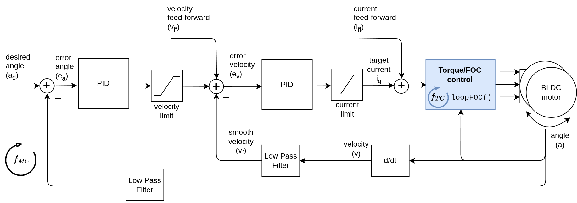
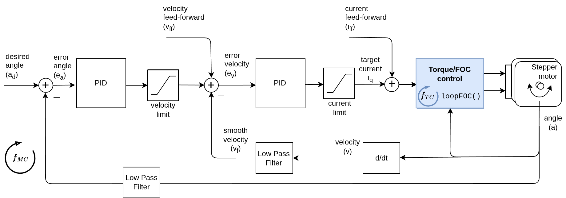
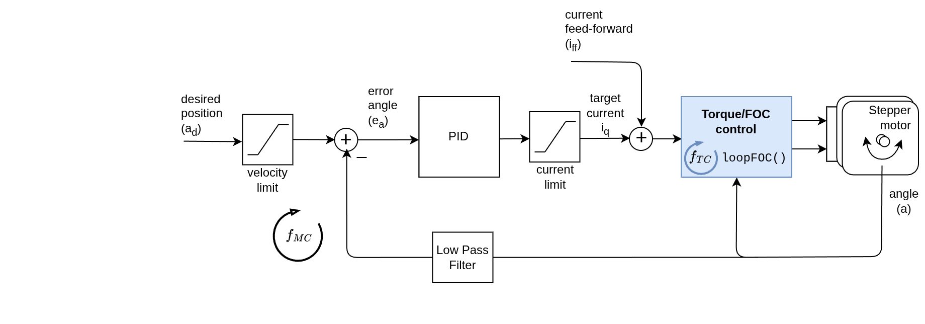
In Cascade position control the angle control loop is closing the loop around the velocity control loop, which is closing the loop around the torque control loop. This means that the angle controller will be setting the velocity target to the velocity controller, and then the velocity controller will be setting the torque target to the torque controller. This angle control loop is therefore created by adding one more control loop in cascade on the velocity control loop like showed on the figure above. The loop is closed by using additional PID controller and an optional low pass filter. The controller reads the angle a from the motor (filters is optionally) and determines which velocity vd the motor should move to reach the desired angle ad set by the user. And then the velocity controller reads the current filtered velocity from the motor vf and sets the torque target (uq voltage or iq current) to the torque control loop, needed to reach the velocity vd, set by the angle loop.
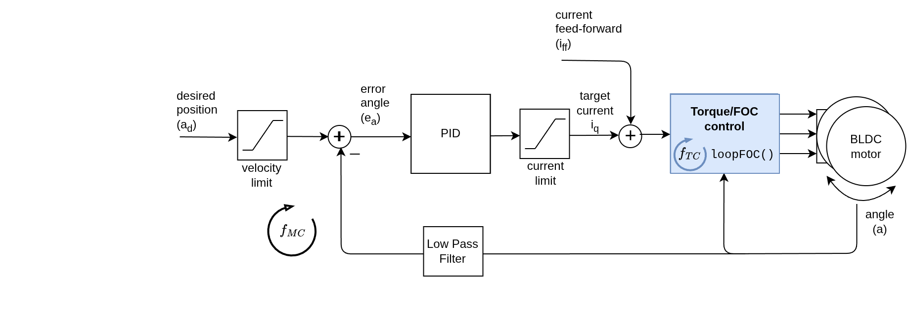
In No-cascade position control the angle control loop is closing the loop directly around the torque control loop. This means that the angle controller will be setting the torque target to the torque controller, without using the velocity controller in between. This angle control loop is created by adding one more control loop on top of the torque control loop like showed on the figure above. The loop is closed by using additional PID controller and an optional low pass filter. The controller reads the angle a from the motor (filters is optionally) and sets the torque target (uq voltage or iq current) to the torque control loop, needed to reach the desired angle ad, set by the angle loop. Comparison of the two strategies
Use-cases for Cascade Position Control:
Go to Cascade Control (Recommended) Use-cases for No-Cascade Position Control:
Go to Non-Cascade Control (Advanced) Table of contents | ||||||||||||
| You are visitor 01402503 — GeezerVison does not store the pages you look up. Best viewed with Netscape Navigator 4.7 or Internet Explorer 6 at 800×600. No cookies required. |